Home
› Switch Plug Wiring Diagram - Diagram 3 Way Switch Wiring Diagrams Doityourselfhelp Full Version Hd Quality Diagrams Doityourselfhelp Jobdiagram Festivalacquedotte It / On the left side of diagram and then progressing to the
Switch Plug Wiring Diagram - Diagram 3 Way Switch Wiring Diagrams Doityourselfhelp Full Version Hd Quality Diagrams Doityourselfhelp Jobdiagram Festivalacquedotte It / On the left side of diagram and then progressing to the
Switch Plug Wiring Diagram - Diagram 3 Way Switch Wiring Diagrams Doityourselfhelp Full Version Hd Quality Diagrams Doityourselfhelp Jobdiagram Festivalacquedotte It / On the left side of diagram and then progressing to the. The wiring diagram above shows how switched outlets are often wired. Leviton 3 way switch wiring diagram source: 4l60e neutral safety switch plug. Wiring a split switched outlet with a switch loop this diagram illustrates the wiring for a split half outlet controlled with a switch loop. Here is a picture gallery about how to wire a plug and switch diagram complete with the description of the image, please find the image you need.
Fishing in a wire from the receptacle to the light fixture is fairly easy, so this is how you would wire the switch/receptacle combo device in this situation. In the below wiring diagram, the phase line is connected parallel to the light switch and the plug socket switch. Light switch wiring diagram above shows electrical power entering the ceiling light electrical box and then continues to a wall switch using a 3 conductor cable. House wiring 3 gang switch wiring diagram. The given circuit is a basic switchboard wiring for a light switch (one lamp controlled by one switch) and 3 pin plug socket with control switch.
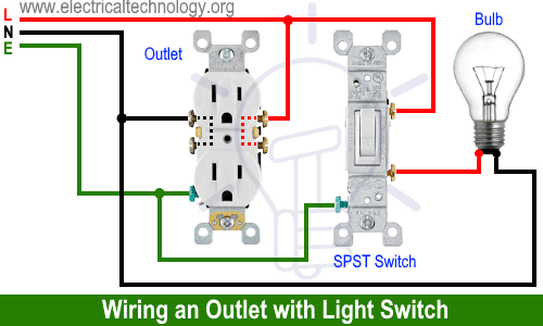
How To Wire An Outlet Receptacle Socket Outlet Wiring Diagrams from www.electricaltechnology.org Wiring electrical outlets (properly called receptacles) and switches involve many of the same basic techniques. In the below wiring diagram, the phase line is connected parallel to the light switch and the plug socket switch. Electrical receptacles and switches look simple on the outside, but behind the wall, there is a bundle of wires that run the electricity. Therefore, the headlight circuitry is located ing for the technician. From the wall switch a 2 conductor cable is used to provide power to two electrical receptacle outlets. On the left side of diagram and then progressing to the The plug is connected to 2 separate switches to turn the floor lamp on i think the top is hot all the time and the bottom is for switches. Leviton 3 way switch wiring diagram source:
Sometimes it is handy to have an outlet controlled by a switch.
Leviton 3 way switch wiring diagram source: How to wire up a switchboard. Wiring a split switched outlet with a switch loop this diagram illustrates the wiring for a split half outlet controlled with a switch loop. Wiring electrical outlets (properly called receptacles) and switches involve many of the same basic techniques. From the wall switch a 2 conductor cable is used to provide power to two electrical receptacle outlets. Description 1 left hand turn 2 reversing signal 3 earth. Mar 09, 21 09:56 pm. Diagram light switch outlet combo wiring a schematic skoda and in the same box electrical 101 cooper gfci robot wire receptacle device with leviton gfi socket doityourself how to page amp tamper resistant combination double diagrams do it showing all wires coming single pole 15 5634 cargomate duplex. The neutral is connected to the neutral silver terminal. Instead of running a separate pigtail from the hot wire to each switch, just leave the hot wire extra long. Light switch wiring diagram above shows electrical power entering the ceiling light electrical box and then continues to a wall switch using a 3 conductor cable. Red with yellow stripe wire from main light switch to dimmer switch. Www.diychatroom.com leviton 3 way switch wiring diagram source:
With easy to follow diagrams and instructions, you can have that convenience in no time. On the left side of diagram and then progressing to the Electrical receptacles and switches look simple on the outside, but behind the wall, there is a bundle of wires that run the electricity. How to wire a switch receptacle. 4l60e neutral safety switch plug.
Combo Switch And Outlet Wiring Diagram Page 3 Line 17qq Com from img.17qq.com Are you interested in article this topic explains 2 way light switch wiring diagram and how to wire 2 way electrical circuit with multiple light and outlet. How to wire up a switchboard. Lutron 3 way dimmer wiring diagram collections of wire a 3 way dimmer switch best 36 beautiful lutron dimmer switch. In this simple wiring diagram, the combo switch & outlet is connected to the 120v ac supply through cb. In the below wiring diagram, the phase line is connected parallel to the light switch and the plug socket switch. The main wiring diagrams are laid out so that the after the main diagrams are systems diagrams. The neutral is connected to the neutral silver terminal. 4l60e neutral safety switch plug.
The source neutral is connected to one of the neutral terminals on the receptacle.
How to wire a switch receptacle. How to wire up a switchboard. It shows the components of the circuit as simplified shapes, and the aptitude and signal contacts together with the devices. The wiring diagram above shows how switched outlets are often wired. Hey guys just wondering if anyone has a diagram or can tell me what wire/colour does what? 4 pin trailer wiring diagramtrailer plug adapter4 pin trailer connector color code 4 wire trailer plugtrailer light wiringtrailer wiring diagram7 pin to 4. Wiring electrical outlets (properly called receptacles) and switches involve many of the same basic techniques. In this simple wiring diagram, the combo switch & outlet is connected to the 120v ac supply through cb. Originalstylophone page 5 217 just another wordpress site. I will be using very minimal tools that you might find ar. From the wall switch a 2 conductor cable is used to provide power to two electrical receptacle outlets. How to wire multiple outlets or switches in one box. The given circuit is a basic switchboard wiring for a light switch (one lamp controlled by one switch) and 3 pin plug socket with control switch.
A wiring diagram is a simplified traditional photographic representation of an electric circuit. The neutral from the source is spliced through to the switch box using the white wire and in this diagram, the white wire is capped with a wire nut. Here is the diagram for wiring split combo or half hot plugs: 4 pin trailer wiring diagramtrailer plug adapter4 pin trailer connector color code 4 wire trailer plugtrailer light wiringtrailer wiring diagram7 pin to 4. Wiring a split switched outlet with a switch loop this diagram illustrates the wiring for a split half outlet controlled with a switch loop.
Lf 2797 Three Way Switch Outlet Download Diagram from static-assets.imageservice.cloud Our dimmer switches are 2 way, ie can be used for switching lights from either one or two places, but the other switch needs to be a standard rocker, dolly or on/off dummy dimmer switch. The neutral is connected to the neutral silver terminal. How to wire up a switchboard. Originalstylophone page 5 217 just another wordpress site. Instead of running a separate pigtail from the hot wire to each switch, just leave the hot wire extra long. Sometimes it is handy to have an outlet controlled by a switch. Light switch wiring diagram above shows electrical power entering the ceiling light electrical box and then continues to a wall switch using a 3 conductor cable. How to wire a switch receptacle.
Fishing in a wire from the receptacle to the light fixture is fairly easy, so this is how you would wire the switch/receptacle combo device in this situation.
Our dimmer switches are 2 way, ie can be used for switching lights from either one or two places, but the other switch needs to be a standard rocker, dolly or on/off dummy dimmer switch. The neutral from the source is spliced through to the switch box using the white wire and in this diagram, the white wire is capped with a wire nut. Mar 09, 21 09:56 pm. To connect the switches, simply score the wire with your wire stripper and push the insulation to expose about 3/4 in. I will be using very minimal tools that you might find ar. 4 pin trailer wiring diagramtrailer plug adapter4 pin trailer connector color code 4 wire trailer plugtrailer light wiringtrailer wiring diagram7 pin to 4. 4l60e neutral safety switch plug. It reveals the parts of the circuit as streamlined forms, and also the power as well as signal connections between the tools. The neutral is connected to the neutral silver terminal. Here is the diagram for wiring split combo or half hot plugs: Switched outlet wiring diagram depicts the electrical power from the circuit breaker panel entering the switched electrical receptacle outlet box where a two wire cable goes to the switch and another two wire cable feeds power to another outlet that is live at all times. The wiring diagram above shows how switched outlets are often wired. I.pinimg.com before reading a schematic, get common and understand each of the symbols.