Schematic Circuit Diagrams - wilbo666 / 1UZ-FE UZS143 Aristo Engine Wiring / Circuitdiagram.net provides huge collection of electronic circuit design :. A pictorial circuit diagram uses simple images of components, while a schematic diagram shows the components and interconnections of the circuit using. See more ideas about electronic schematics, circuit diagram, electronics. Alarm, amplifier, digital circuit, power supply, inverter, radio, robot and more. With the increasing complexity of electronic circuitry, discrete functional blocks, such as relays, are often represented as 'black boxes' on the overall schematic diagrams with only. Symbols that represent the components in the circuit, and lines that represent the connections.
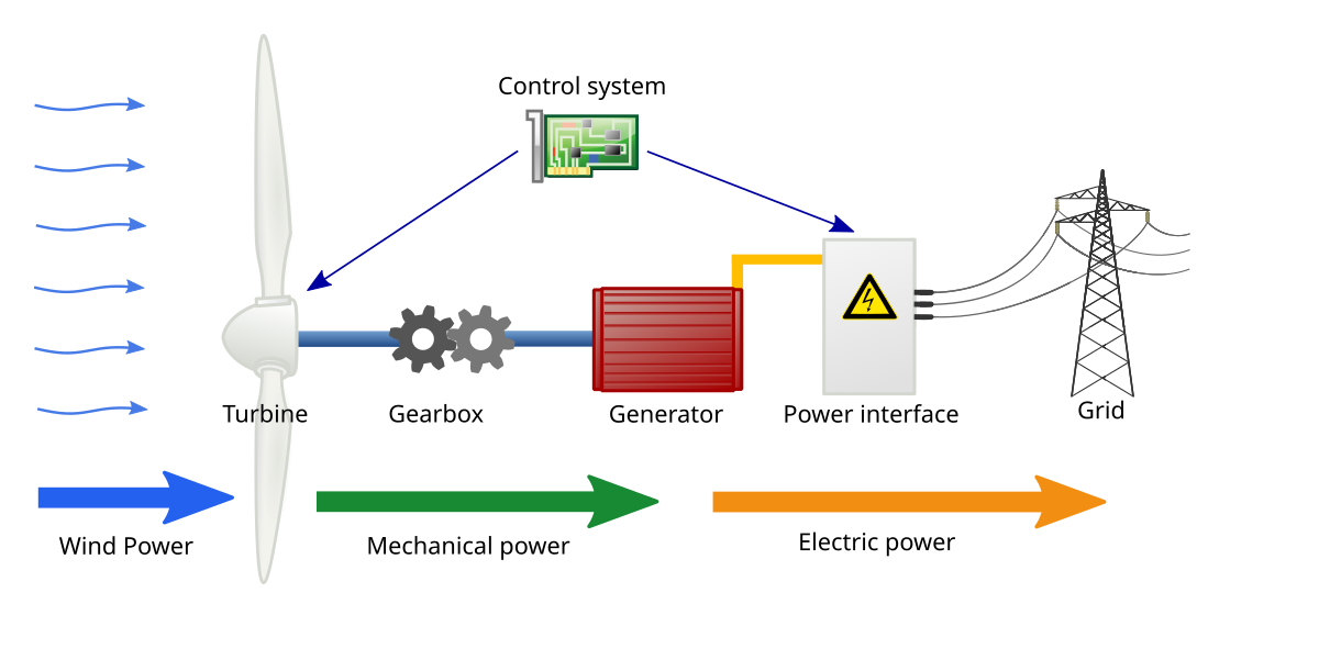
File:Wind turbine schematic.svg - Wikimedia Commons from upload.wikimedia.org Professional schematic pdfs, wiring diagrams, and plots. This is a simplest fm transmitter circuit schematic with a single transistor. With electric circuits and circuit diagrams, the length and routing of wire connecting components in a circuit matters little. Visit this page regularly for latest updates of projects. With the increasing complexity of electronic circuitry, discrete functional blocks, such as relays, are often represented as 'black boxes' on the overall schematic diagrams with only. After seeing a few circuit diagrams, you'll quickly learn how to distinguish the different symbols. To simplify a convoluted circuit schematic, follow these. These two different types of circuit diagrams are called pictorial (using basic images) or schematic style (using.
A circuit diagram, or a schematic diagram, is a technical drawing of how to connect electronic components to get a certain function.
A circuit diagram also known as an electrical diagram, wiring diagram, elementary diagram, or electronic schematic is a simplified conventional pictorial representation of an electrical circuit. Symbol usage depends on the audience viewing the diagram. The circuit in the diagram provides an output voltage of 5 v and is supplied by a 24 v source. You may have heard them very often, but they vary each other slightly. With the increasing complexity of electronic circuitry, discrete functional blocks, such as relays, are often represented as 'black boxes' on the overall schematic diagrams with only. Circuit diagrams show the connections as clearly as possible with all wires drawn neatly as straight lines. One of the clocks is wired as an astable multivibrator to produce the. Pwm or pulse width modulation is a very common method used for controlling the power. See more ideas about electronic schematics, circuit diagram, electronics. Circuitscheme.com provides the collection of electronic circuit schematic design for hobbyst; Symbols that represent the components in the circuit, and lines that represent the connections. The regulator need not be disabled until the capacitor is fully charged: Schematic diagrams describe the main and auxiliary circuits for control, signalling, monitoring and protection systems.
A pictorial circuit diagram uses simple images of components. 24v to 220v 1000w dc ac sine wave inverter for photovoltaic solar system. Analog & digital circuit simulations in seconds. This physics video tutorial explains how to read a schematic diagram by knowing what each electric symbol represent in a typical electrical circuit. This is a simplest fm transmitter circuit schematic with a single transistor.
Printed Circuit Board Lying On Diagram Of Electronics Technology Stock Photo - Download Image ... from media.istockphoto.com These two different types of circuit diagrams are called pictorial (using basic images) or schematic style (using. Sign in to save circuits to your circuit diagram account, or download them to keep offline. In this blog post, i try to combine this year's new information for you to download and read mobile phone circuit diagrams and repair your mobile phones. Alarm, amplifier, digital circuit, power supply, inverter, radio, robot and more. This is a simplest fm transmitter circuit schematic with a single transistor. Design circuits online in your browser or using the desktop application. Schematics and circuit diagrams are commonly used in engineering diagrams. The actual layout of the components is usually quite a circuit diagram is useful when testing a circuit and for understanding how it works.
The circuit in the diagram provides an output voltage of 5 v and is supplied by a 24 v source.
The circuit in the diagram provides an output voltage of 5 v and is supplied by a 24 v source. When the potential across the capacitor has reached a level of half or more of the input. Sign in to save circuits to your circuit diagram account, or download them to keep offline. With electric circuits and circuit diagrams, the length and routing of wire connecting components in a circuit matters little. Alarm, amplifier, digital circuit, power supply, inverter, radio, robot and more. Switched on bike lamp circuit diagram: They serve as a map or plan for schematic diagrams are made up of two things: A circuit diagram (also named electrical diagram, elementary diagram, and electronic schematic) is a graphical representation of an electrical circuit. Circuit diagrams show the connections as clearly as possible with all wires drawn neatly as straight lines. Circuitdiagram.net provides huge collection of electronic circuit design : Circuitdiagram a circuit diagram ( also known as an electrical diagram , elementary diagram , or electronic schematic ) is a simplified conventional graphical representation of an electrical circuit. Simply click edit on a template and then customize it to fit your needs. 12v fan on 230v circuit.
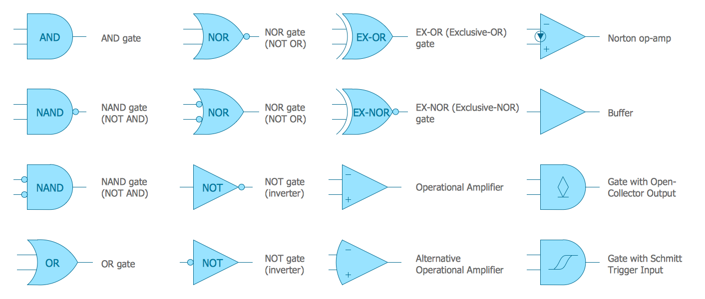
Symbol usage depends on the audience viewing the diagram. This physics video tutorial explains how to read a schematic diagram by knowing what each electric symbol represent in a typical electrical circuit. A circuit diagram, or a schematic diagram, is a technical drawing of how to connect electronic components to get a certain function. Circuit diagram of '10w amplifier circuit using ic tda2030' with power supply. This is a simplest fm transmitter circuit schematic with a single transistor.
Wiring Diagram with ConceptDraw DIAGRAM from www.conceptdraw.com R1 = photo resistor (any type) r2 = 22k 1/2w trimmer cermet… A circuit diagram also known as an electrical diagram, wiring diagram, elementary diagram, or electronic schematic is a simplified conventional pictorial representation of an electrical circuit. Alarm, amplifier, digital circuit, power supply, inverter, radio, robot and more. Symbol usage depends on the audience viewing the diagram. Sign up to design, share, and collaborate on your next project—big or small. With the increasing complexity of electronic circuitry, discrete functional blocks, such as relays, are often represented as 'black boxes' on the overall schematic diagrams with only. Wires in diagrams and in real circuits can be lengthened, shortened, and/or moved without affecting circuit operation. Pwm motor speed control using arduino schematic circuit diagram.
Circuit diagram of '10w amplifier circuit using ic tda2030' with power supply.
Circuitdiagram a circuit diagram ( also known as an electrical diagram , elementary diagram , or electronic schematic ) is a simplified conventional graphical representation of an electrical circuit. Professional schematic pdfs, wiring diagrams, and plots. Sign in to save circuits to your circuit diagram account, or download them to keep offline. Alarm, amplifier, digital circuit, power supply, inverter, radio, robot and more. Circuitspediaelectronic tutorials, circuit diagram, projects etc. They serve as a map or plan for schematic diagrams are made up of two things: With the increasing complexity of electronic circuitry, discrete functional blocks, such as relays, are often represented as 'black boxes' on the overall schematic diagrams with only. Schematic diagrams describe the main and auxiliary circuits for control, signalling, monitoring and protection systems. Sign up to design, share, and collaborate on your next project—big or small. With electric circuits and circuit diagrams, the length and routing of wire connecting components in a circuit matters little. R1 = photo resistor (any type) r2 = 22k 1/2w trimmer cermet… Analog & digital circuit simulations in seconds. It's built on a pc board that measures just.