Home
› 5 Pin Trailer Plug Wiring Diagram / Trailer Wiring Diagram 5 Core Wiring Diagrams 86 Ford Bronco 2 Heaterrelaay Tukune Jeanjaures37 Fr / It reveals the components of the circuit as streamlined shapes, and also the power and also signal links in between the gadgets.
5 Pin Trailer Plug Wiring Diagram / Trailer Wiring Diagram 5 Core Wiring Diagrams 86 Ford Bronco 2 Heaterrelaay Tukune Jeanjaures37 Fr / It reveals the components of the circuit as streamlined shapes, and also the power and also signal links in between the gadgets.
5 Pin Trailer Plug Wiring Diagram / Trailer Wiring Diagram 5 Core Wiring Diagrams 86 Ford Bronco 2 Heaterrelaay Tukune Jeanjaures37 Fr / It reveals the components of the circuit as streamlined shapes, and also the power and also signal links in between the gadgets.. Are now using 5 wire flat plug wiring to be more compatible with 4 and 5 wire vehicles. The 7 pin flat plug will fit into a 12 pin flat socket and work perfectly. Wiring diagram trailer _ sabs 7core.cdr author: 1996 acura rl fuse box diagram fuse box diagram bmw x5 2007 2001 yamaha. Use on a small motorcycle trailer, snowmobile trailer or utility trailer.
4 pin trailer wiring diagram. Wiring diagram for wiring in trailer plugs and sockets. Obtaining from factor a to point b. Above we have describes the main types of trailer wiring diagrams. Wiring diagram for six pin trailer plug 2019 trailer connector.
Wiring Diagram For 7 Pin Trailer Connector Ford 250 Wiring Diagram Database Evening from i0.wp.com So i would suggest using a 7 pin wiring diagram and simply ignore blue and black. The red and blue wire can be used for brake control or auxiliary. How to wire a 7 pin trailer plug (diagram shown) All diagrams are as viewed from the cable side. The function is the same: Details for small round 6 pin and 7 pin, flat 12 pin and flat 7 pin; Assortment of 5 pin boat trailer wiring diagram. And 7 pin large round.
Trailer side car side wiring plug diagram.
12 pin flat this is an extension of the 7 pin flat. Assortment of hopkins trailer plug wiring diagram. All diagrams are as viewed from the cable side. A first appearance at a circuit representation might be confusing, however if you could review a train map, you could review schematics. This type of plug and socket is also an older type and vehicles that were first registered before january 1988 commonly used a 6 pin type. 7 pin flat the best! Wiring layouts are made up of 2 points: Start by cutting the white wire and attaching it to the trailer frame. How to wire a 7 pin trailer plug (diagram shown) However, it doesn't have as sophisticated and electric intensive attributes that rv and other expensive trailers might have. Trailer side car side wiring plug diagram. 7 2 6 5 4 3. 1996 acura rl fuse box diagram fuse box diagram bmw x5 2007 2001 yamaha.
Wiring layouts are made up of 2 points: 12 pin flat this is an extension of the 7 pin flat. Assortment of 5 pin boat trailer wiring diagram. The red and blue wire can be used for brake control or auxiliary. Wiring diagram for wiring in trailer plugs and sockets.
Trailer Connectors In Australia Wikipedia from upload.wikimedia.org The red and blue wire can be used for brake control or auxiliary. It reveals the components of the circuit as simplified shapes, as well as the power and also signal connections between the tools. Above we have describes the main types of trailer wiring diagrams. Wiring diagram for wiring in trailer plugs and sockets. 6 way system, rectangle plug. Trailer side car side wiring plug diagram. You must check the trailer manual to see if the wiring is correct, but normally the white wire is called the ground wire, while the brown wire is used for tail lights. And 7 pin large round.
The red and blue wire can be used for brake control or auxiliary.
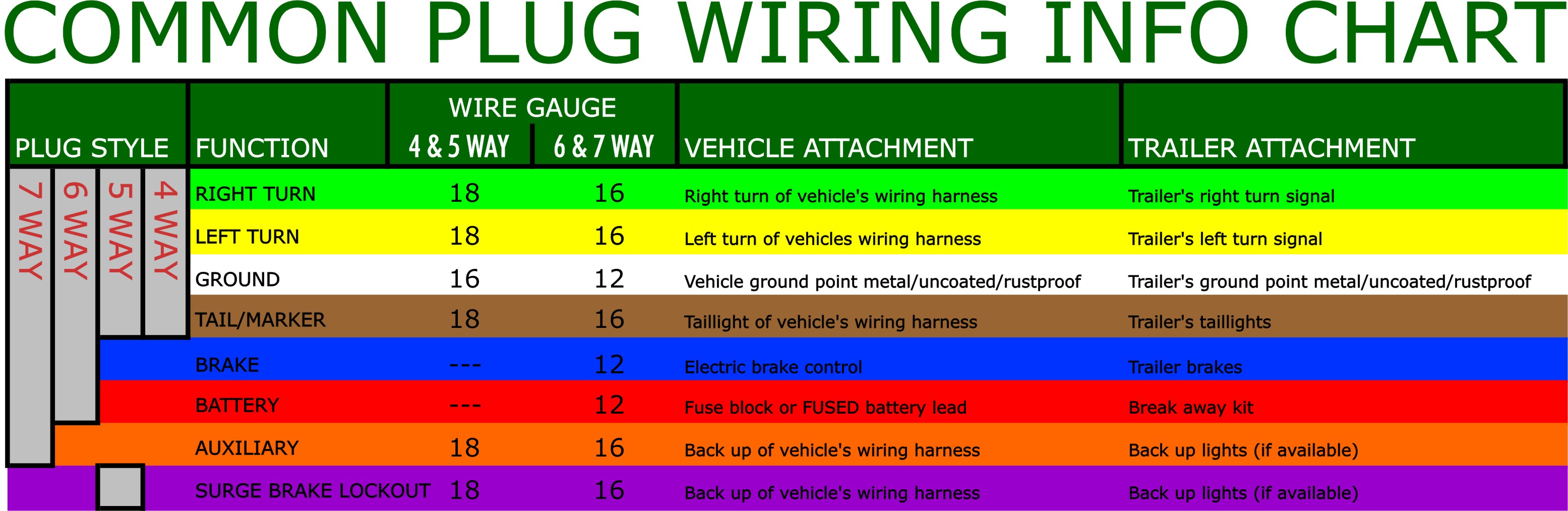
Yellow and green are for left and right turns and braking. Literally, a circuit is the path that allows electricity to circulation. Obtaining from factor a to point b. How to wire a 7 pin trailer plug (diagram shown) A first appearance at a circuit representation might be confusing, however if you could review a train map, you could review schematics. 7 way plug wiring diagram standard wiring* post purpose wire color tm park light green (+) battery feed black rt right turn/brake light brown lt left turn/brake light red s trailer electric brakes blue gd ground white a accessory yellow this is the most common (standard) wiring scheme for rv plugs and the one used by major auto manufacturers today. Are now using 5 wire flat plug wiring to be more compatible with 4 and 5 wire vehicles. The 7 pin flat plug will fit into a 12 pin flat socket and work perfectly. Australian trailer plug and socket wiring diagrams. This type of plug and socket is also an older type and vehicles that were first registered before january 1988 commonly used a 6 pin type. So i would suggest using a 7 pin wiring diagram and simply ignore blue and black. 12 pin flat this is an extension of the 7 pin flat. Start by cutting the white wire and attaching it to the trailer frame.
Trailer wiring diagrams trailer wiring connectors various connectors are available from four to seven pins that allow for the transfer of power for the lighting as well as auxiliary functions such as an electric trailer brake controller, backup lights, or a 12v power supply for a winch or interior trailer lights. Assortment of 5 pin boat trailer wiring diagram. However, it doesn't have as sophisticated and electric intensive attributes that rv and other expensive trailers might have. Are now using 5 wire flat plug wiring to be more compatible with 4 and 5 wire vehicles. Signs that represent the elements in the circuit, and lines that represent the links in.
What Are The Most Common Trailer Plugs from www.hitchweb.com Wiring diagram trailer _ sabs 7core.cdr author: Assortment of 5 pin boat trailer wiring diagram. They can be purchased as a standalone plug for the truck or trailer, or as a complete loop with both the plug and the socket included. This type of connector is normally found on utvs, atvs and trailers that do not have their own braking system. Are now using 5 wire flat plug wiring to be more compatible with 4 and 5 wire vehicles. You must check the trailer manual to see if the wiring is correct, but normally the white wire is called the ground wire, while the brown wire is used for tail lights. A wiring diagram is a simplified traditional photographic representation of an electrical circuit. Trailer side car side wiring plug diagram.
3/4 inch by 1 inch 6 way rectangle connectors right turn signal (green), left turn signal (yellow), taillight (brown), ground (white).
/ i have a 7 flat connector and would like to put a batt. 4 pin trailer wiring diagram. Literally, a circuit is the path that allows electricity to circulation. A wiring diagram is a simplified traditional photographic representation of an electrical circuit. Obtaining from factor a to point b. 1996 acura rl fuse box diagram fuse box diagram bmw x5 2007 2001 yamaha. Below is the generic schematic of how the wiring goes. Details for small round 6 pin and 7 pin, flat 12 pin and flat 7 pin; Wiring diagram for six pin trailer plug 2019 trailer connector. The 5th pin, a blue wire, gives power to operate (or disable) the trailer brakes. However, it doesn't have as sophisticated and electric intensive attributes that rv and other expensive trailers might have. But, it doesn't possess as sophisticated and electrical consuming features that rv and other costly trailers might have. Assortment of hopkins trailer plug wiring diagram.