Home
› 4 Pin Micro Relay Wiring Diagram - How To Wire A Relay For Off Road Led Lights Off Road Led Lights Relay Electrical Diagram : Note that each pin is numbered.
4 Pin Micro Relay Wiring Diagram - How To Wire A Relay For Off Road Led Lights Off Road Led Lights Relay Electrical Diagram : Note that each pin is numbered.
4 Pin Micro Relay Wiring Diagram - How To Wire A Relay For Off Road Led Lights Off Road Led Lights Relay Electrical Diagram : Note that each pin is numbered.. This list covers single pole single throw (spst) relays, single pole double throw (spdt) relays, and double pole double throw (dpdt) relays. Each component ought to be set and connected with different parts in particular way. 12 volt wiring diagram best 12v relay pin 5 and roc grp org in. If you need a relay diagram that is not included in the 76 relay wiring diagrams shown below, please search our forums or post a request for a new relay diagram in our relay forum. But in all pins, we have two for the coil.
This list covers single pole single throw (spst) relays, single pole double throw (spdt) relays, and double pole double throw (dpdt) relays. Looking at the diagram, we see the pinout of a typical 12v relay. The iso defines this type of relay as 1 inch (2.5 cm) by 1 inch (2.5 cm) by 0.5 inches (25.4 mm by 25.4 mm by 12.7 mm). 4 pin relay wiring diagram autok dpdt double pole double throw relay pin diagram relay pole best relay wiring diagram 5 pin bosch endearing enchanting stage 4 complete beginner s guide for arduino hardware platform simple relaycircuit is an electrically operated switch many electrical repair services electricity automotive electrical great wiring diagram for horn relay horn relay simple wiring. If the coil is not activated, 30 will always be connected to 87a.
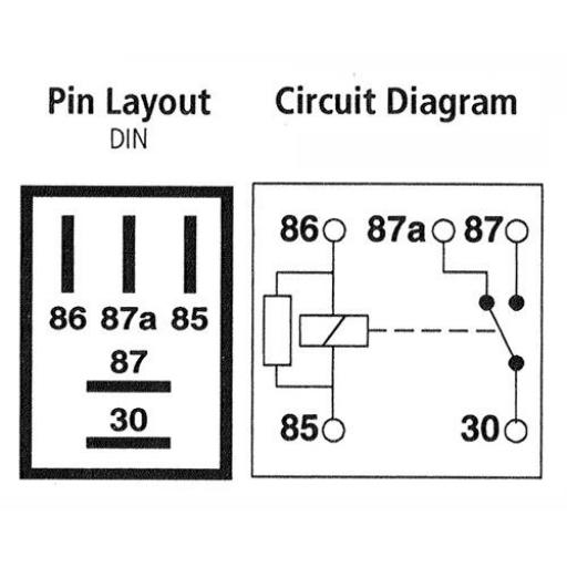
Micro Relay 5 Pin Changeover 12v 20a With Resistor Car Automotive Auto Micro Relay Make And Break Car Van Bike Boat from bits4work-static.myshopblocks.com Note that each pin is numbered. An iso micro relay has the control circuit connected to pin 86 and pin 85, and the load circuit connected to pin 30 and pin 87 or 87a. Hvac fan relay wiring diagram download. 85 and 86 are the coil pins while 30, 87, and 87a are the contact pins. Otherwise, the structure won't function as it ought to be. A few people have asked what gets connected to the different connectors on a relay. Well, since i had an idea, but wasnt 100% sure, i did some reading and de. Determine that the relay is an iso micro type.
Normally open or normally closed.
4 pin relay 4 pin relays use 2 pins (85 & 86) to control the coil and 2 pins (30 & 87) which switch power on a single circuit. This list covers single pole single throw (spst) relays, single pole double throw (spdt) relays, and double pole double throw (dpdt) relays. In this post, i am sharing a simple 5 pin relay wiring diagram. An iso micro relay has the control circuit connected to pin 86 and pin 85, and the load circuit connected to pin 30 and pin 87 or 87a. Protective relays can prevent equipment damage by detecting electrical abnormalities, including overcurrent, undercurrent, overloads and reverse currents. Dozens of the most popular 12v relay wiring diagrams created for our site and members all in one place. Understanding timer delay relay function. These contacts are pin can 4, 5, 8, 11, 14, etc. A few people have asked what gets connected to the different connectors on a relay. Hvac fan relay wiring diagram download. Note that each pin is numbered. Where we provide the required ratting current. 5 pin micro relay 4 pin micro relay
There are 2 types of 4 pin relay available; Note that each pin is numbered. Understanding timer delay relay function. In addition, these are also widely used to switch starting coils, heating elements, pilot lights and audible alarms. Below are the diagrams for connecting the various types of relays.
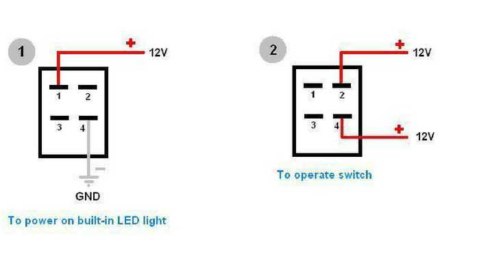
Diy Bussmann Rtmr Fuse Block Part 4 Wiring And Schematics Bodenzord from www.bodenzord.com I know all about this stuff Wiring a rocker switch depends on the type you plan on using, so your wiring will depend on the amount of pins your rocker switch has. Dozens of the most popular 12v relay wiring diagrams created for our site and members all in one place. Note that each pin is numbered. A few people have asked what gets connected to the different connectors on a relay. 4 pin relay wiring diagram autok dpdt double pole double throw relay pin diagram relay pole best relay wiring diagram 5 pin bosch endearing enchanting stage 4 complete beginner s guide for arduino hardware platform simple relaycircuit is an electrically operated switch many electrical repair services electricity automotive electrical great wiring diagram for horn relay horn relay simple wiring. Where we provide the required ratting current. Understanding timer delay relay function.
It's can be according to the pins, or contacts, ampers, voltage ratting (ac or dc).
Note that each pin is numbered. The iso defines this type of relay as 1 inch (2.5 cm) by 1 inch (2.5 cm) by 0.5 inches (25.4 mm by 25.4 mm by 12.7 mm). Relays are devices making or braking electric circuits by their output section driven by operational signal, which is triggered by electric input signal controlled by switching devices. 4 pin relay wiring diagram autok dpdt double pole double throw relay pin diagram relay pole best relay wiring diagram 5 pin bosch endearing enchanting stage 4 complete beginner s guide for arduino hardware platform simple relaycircuit is an electrically operated switch many electrical repair services electricity automotive electrical great wiring diagram for horn relay horn relay simple wiring. Both 4 and 5 pins designs are used. Each component ought to be set and connected with different parts in particular way. Normally open or normally closed. Looking at the diagram, we see the pinout of a typical 12v relay. Understanding all the time delay relay functions available in multifunctional timer can be an intimidating task. 4 pin relay 4 pin relays use 2 pins (85 & 86) to control the coil and 2 pins (30 & 87) which switch power on a single circuit. Numbers of a relay looking at the diagram, we see the pinout of a typical 12v relay. 87 and 87a are the two contacts. 4 pin led switch wiring shouldn't cause any headaches if you follow the right diagram.
Understanding timer delay relay function. Protection diode and spike suppression resistor for automotive relays Note that each pin is numbered. In addition, these are also widely used to switch starting coils, heating elements, pilot lights and audible alarms. 4 pin led switch wiring shouldn't cause any headaches if you follow the right diagram.
How To Wire 4 Pin Led Switch 4 Pin Led Switch Wiring from www.oznium.com 87 and 87a are the two contacts to which 30 will connect. Understanding all the time delay relay functions available in multifunctional timer can be an intimidating task. 87 and 87a are the two contacts. If the coil is not activated, 30 will always be connected to 87a. Optronics 40 amp 4 pin relay wiring diagram fusebox and cable title haskee it. Pin diagram spdt relay switch dpdt relay switch. Where we provide the required ratting current. 85 and 86 are the coil pins while 30, 87, and 87a are the switch pins.
I know all about this stuff
Where we provide the required ratting current. Relay is available in different shapes and types. Diagram 4 pin relay wiring wire fusebox and 5 horn full 12v page 1 pole 40a bosch denso micro pinout china 30 amp 12 volt reed how to a step by 2 flasher automotive car relays in optronics 40 honeywell r8222u diagrams maa2 s 3 zm 7629 5v description working door locks alternating flashers hazards omron timer aux. Protection diode and spike suppression resistor for automotive relays Note that each pin is numbered. These contacts are pin can 4, 5, 8, 11, 14, etc. Hvac fan relay wiring diagram download. 87 and 87a are the two contacts. Below are the diagrams for connecting the various types of relays. Here is a picture gallery about relay 4 pin wiring diagram complete with the description of the image, please find the image you need. 85 and 86 are the coil pins while 30, 87, and 87a are the contact pins. Both 4 and 5 pins designs are used. A normally open relay will switch power on for a circuit when the coil is activated.