Home
› Wiring Vfd Motor Control Circuit Diagram / Abb Vfd Wiring Diagram Collection | Wiring Collection : Automation dc motor e inversion control circuit, the circuit loop l li kdl dc brush motor driver circuit diagram mc33035 chip using a straight debate brush motor driving circuit ring shows.
Wiring Vfd Motor Control Circuit Diagram / Abb Vfd Wiring Diagram Collection | Wiring Collection : Automation dc motor e inversion control circuit, the circuit loop l li kdl dc brush motor driver circuit diagram mc33035 chip using a straight debate brush motor driving circuit ring shows.
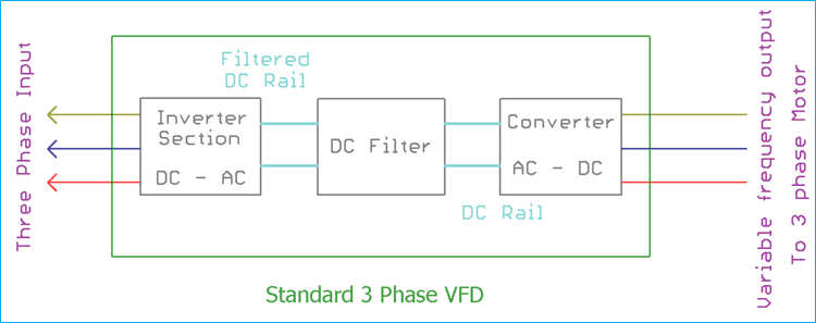
Wiring Vfd Motor Control Circuit Diagram / Abb Vfd Wiring Diagram Collection | Wiring Collection : Automation dc motor e inversion control circuit, the circuit loop l li kdl dc brush motor driver circuit diagram mc33035 chip using a straight debate brush motor driving circuit ring shows.. For wiring of the inverter, it is divided into the main circuit and the. Sa video tutorial na ito ay gagawa po tayo ng control wiring diagram para po sa motor control circuit ng vfd or variable. They must not be fed through the 3.1 basic wiring diagram. Standard stepper drive and motor. Sa video tutorial na ito ay gagawa po tayo ng control wiring diagram para po sa motor control circuit ng vfd or variable.
Danfoss vfd control wiring diagram. 34 control interface 15 35 wiring schematic 16 36 controls 18 361 control principle 18 362 fc 301 vs. Do not plug a modem or telephone. They must not be fed through the 3.1 basic wiring diagram. The control leads must be routed separately from the power supply and motor leads.
Wiring Vfd Motor Control Circuit Diagram - Wiring Diagram Schemas from circuitdigest.com Motor control circuit variable speed control circuit electricity site. For wiring of the inverter, it is divided into the main circuit and the. Standard stepper drive and motor. The vfd shall include a motor flux optimization circuit that will automatically reduce applied. Complete technical product description include a 12. The vfd inside will vary in voltage, horsepower, full load amps (fla), and other specifications. Refer to the basic wiring diagram. Motor control circuits are an effective way to reduce cost by using smaller wire and reduced amperage devices to control a motor.
S bharadwaj reddyaugust 1, 2017october 5, 2018.
This page contain electronic circuits about motor control circuits at category motor control circuit : Users must connect wiring according to the circuit diagram shown below. 34 control interface 15 35 wiring schematic 16 36 controls 18 361 control principle 18 362 fc 301 vs. Refer to the basic wiring diagram. Gk3000 series variable frequency drive (vfd) adopts speed sensorless vector control technology to offer excellent control performance, enhances operation reliability and environment adaptability. Tr1™ series vfd variable frequency drive. Please ecsess the circuit diagram of vfd for 50kw moter oprating. Motor control circuit variable speed control circuit electricity site. A wiring diagram is a straightforward visual representation with the physical connections and physical layout of an electrical system or circuit. Automation dc motor e inversion control circuit, the circuit loop l li kdl dc brush motor driver circuit diagram mc33035 chip using a straight debate brush motor driving circuit ring shows. The control leads must be routed separately from the power supply and motor leads. Main circuit wiring schematic diagram(图标自己加). S bharadwaj reddyaugust 1, 2017october 5, 2018.
Vfd wiring involves main circuit and control circuit. Users must connect wires according to the circuit diagrams on the. V70 series high performance vector control mini vfd. Recommended maximum switching on input is 2 times per minute charge circuits may heat up with. Refer to the basic wiring diagram.
Wiring Diagram For Vfd from i0.wp.com Please ecsess the circuit diagram of vfd for 50kw moter oprating. Normal ac supply to motor. During controlled deceleration, motor regenerative losses are dissipated in the motor, wire, and vfd circuitry. (1) control terminal block designations. Vfd motor diagram great installation of wiring diagram. Users must connect wires according to the circuit diagrams on the. Sa video tutorial na ito ay gagawa po tayo ng control wiring diagram para po sa motor control circuit ng vfd or variable. For power, signal, and control wiring.
Main circuit wiring schematic diagram(图标自己加).
The control leads must be routed separately from the power supply and motor leads. Sa video tutorial na ito ay gagawa po tayo ng control wiring diagram para po sa motor control circuit ng vfd or variable. This entire assembly consisting of contactor, overload block, control power transformer, power fuses. The vfd shall include a motor flux optimization circuit that will automatically reduce applied. Users must connect wires according to the circuit diagrams on the following pages. Complete technical product description include a 12. Vfd wiring involves main circuit and control circuit. Output line reactors protect the motor insulation against drive short circuits and igbt reflective wave damage. Output line reactors also smooth the motor current waveform, allowing the motor to run cooler. For power, signal, and control wiring. Verify that the inverter's rated voltage coincides with ac power supply voltage 2 for control circuit wiring (signal line) the signal line should be separately laid in a different conduit with the main circuit wire to avoid any possible. Recommended maximum switching on input is 2 times per minute charge circuits may heat up with. Explanation of plc programming to control vfd.
Before using gk3000 vfd, please follow the instruction of this user manual. During controlled deceleration, motor regenerative losses are dissipated in the motor, wire, and vfd circuitry. The vfd inside will vary in voltage, horsepower, full load amps (fla), and other specifications. January 3, 2017 at 6:04 am. Motor control circuits are an effective way to reduce cost by using smaller wire and reduced amperage devices to control a motor.
Wiring Vfd Motor Control Circuit Diagram - Wiring Diagram Schemas from homemade-circuits.com Output line reactors protect the motor insulation against drive short circuits and igbt reflective wave damage. The drawing for vfd start stop wiring diagram from panel.vfds are called as variable frequency i am here with giving you a vfd start stop wiring diagram for running a vfd through panel board the vfds are working based on changing the input frequency and input voltage of the motor, we can. Main circuit wiring schematic diagram(图标自己加). (1) control terminal block designations. Motor control circuit variable speed control circuit electricity site. Gk3000 series variable frequency drive (vfd) adopts speed sensorless vector control technology to offer excellent control performance, enhances operation reliability and environment adaptability. Standard stepper drive and motor. Users must connect wires according to the circuit diagrams on the.
V70 series high performance vector control mini vfd.
Note run input power, motor wiring and control wiring in three separate metallic conduits or raceways for high. Standard stepper drive and motor. The drawing for vfd start stop wiring diagram from panel.vfds are called as variable frequency i am here with giving you a vfd start stop wiring diagram for running a vfd through panel board the vfds are working based on changing the input frequency and input voltage of the motor, we can. Output line reactors protect the motor insulation against drive short circuits and igbt reflective wave damage. Complete technical product description include a 12. Gk3000 series variable frequency drive (vfd) adopts speed sensorless vector control technology to offer excellent control performance, enhances operation reliability and environment adaptability. V70 series high performance vector control mini vfd. Sa video tutorial na ito ay gagawa po tayo ng control wiring diagram para po sa motor control circuit ng vfd or variable. Users must connect wiring according to the circuit diagram shown below. When installing multiple ac motor drives in the same basic wiring diagrams. This page contain electronic circuits about motor control circuits at category motor control circuit : Main circuit wiring schematic diagram(图标自己加). Used ladder logic as plc programming language.