Home
› Logic Gates Diagram And Truth Table / Logic Gates Truth Tables Exercises | Brokeasshome.com - Logic gates are takes some time delay to produce output from input.
Logic Gates Diagram And Truth Table / Logic Gates Truth Tables Exercises | Brokeasshome.com - Logic gates are takes some time delay to produce output from input.
Logic Gates Diagram And Truth Table / Logic Gates Truth Tables Exercises | Brokeasshome.com - Logic gates are takes some time delay to produce output from input.. Below shows the circuit symbol, boolean function, and truth. Logic circuits are designed to perform a particular function, understanding the nature of that function requires a logic circuit truth table. In this post you will predict the output of logic gates circuits by completing truth tables. The operation of the above digital logic gates and their boolean expressions can be summarised into a single truth table as shown below. The diagrams below show two ways that the nand logic gate can be configured to produce a not gate.
The operation of the above digital logic gates and their boolean expressions can be summarised into a single truth table as shown below. Electronic logic gates are comes in integrated circuits (ic) package. Every logic gate operations are stated by its truth table, and it is like a input and. A logic gate can be represented by a block diagram as shown in figure. Comparing the truth table with the written description in describing the action of logic gates (above) it can be seen that the truth table follows the written each animated diagram shows the input and output conditions for one of the seven logic functions in its two input form.
Example of a logic circuit and corresponding truth tables ... from www.researchgate.net Logic gates are defined as the basic building blocks of any digital circuit. It can also be done using nor logic table 2 is a summary truth table of the input/output combinations for the not gate together with all possible input/output combinations for the other gate. Electronic logic gates are comes in integrated circuits (ic) package. Карусель назад следующее в карусели. Not gate is also known as inverter. The truth table is a table of all possible combinations of the variables showing the relation between the values that variables may take and the result of the operation. Logic gates are the key elements of any digital system. The state of output signal depended on the combination of input signal.
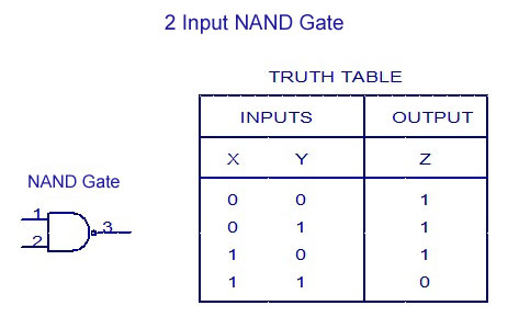
An and gate followed by a not gate operates as a nand gate.
The truth table is a table of all possible combinations of the variables showing the relation between the values that variables may take and the result of the operation. Below shows the circuit symbol, boolean function, and truth. It can also be done using nor logic table 2 is a summary truth table of the input/output combinations for the not gate together with all possible input/output combinations for the other gate. Nor gate (circuit diagram and truth table) video lecture from chapter logic gates of subject application of electronics class 12 subject for hsc, cbse. How can i make a logic circuit any logic block with n inputs will have a row in its karnaugh mapping (formal name for truth table) for every possible combination of input states. Logic gates are the fundamental building blocks of digital electronics. Logic gates act as switches in a circuit that performs logical operation. It has one output and n input (n > = 2). When a logic gate has only two inputs, or the logic circuit to be analyzed has only one or two gates, it is fairly easy to remember how a. The figure shows a circuit that performs an and operation. Block diagram of nand gate. These can be helpful if you are trying to select a suitable gate. In practice, each logic gate is represented by a symbol with input a truth table is used to record all the possible combinations of inputs and the corresponding output decisions for a particular logic circuit.
Logic gates are the basic building blocks of the digital system. It is an electronic circuit that has one or more than one input but only one output. In practice, each logic gate is represented by a symbol with input a truth table is used to record all the possible combinations of inputs and the corresponding output decisions for a particular logic circuit. Logic gates are takes some time delay to produce output from input. When a logic gate has only two inputs, or the logic circuit to be analyzed has only one or two gates, it is fairly easy to remember how a.
Digital Electronics-Logic Gates Basics,Tutorial,Circuit ... from www.circuitstoday.com Документы, похожие на «lec 6a logic gates truth tables and timing diagrams.pdf». Every logic gate operations are stated by its truth table, and it is like a input and. The table used to represent the boolean expression of a logic gate function called a truth table. The logic diagram consists of gates and symbols that can directly replace an expression in boolean arithmetic. Logic gates are the fundamental building blocks of digital electronics. Basically, there are seven types of logic gates as below. It is an electronic circuit having one or more than one input and only one output. Start studying logic gates / truth tables.
It has one input a and one output y.
The truth table is a table of all possible combinations of the variables showing the relation between the values that variables may take and the result of the operation. A truth table shows each possible input. It is an electronic circuit with one or more inputs and one output only. Truth table of or gate. What is logic diagram and truth table? It can also be done using nor logic table 2 is a summary truth table of the input/output combinations for the not gate together with all possible input/output combinations for the other gate. Electronic logic gates are comes in integrated circuits (ic) package. You can click on the truth tables to change the values in the x column. Draw the truth table and gate diagram also provide two examples from daily life? Logic gates definitions, types, symbols and truth tables are discussed. When a logic gate has only two inputs, or the logic circuit to be analyzed has only one or two gates, it is fairly easy to remember how a. Learn vocabulary, terms and more with flashcards, games and other study tools. First you need to learn the basic truth tables for the following logic gates your task is to complete the truth tables for the following diagrams.
An and gate followed by a not gate operates as a nand gate. Nor gate (circuit diagram and truth table) video lecture from chapter logic gates of subject application of electronics class 12 subject for hsc, cbse. A truth table shows each possible input. Electronic logic gates are comes in integrated circuits (ic) package. Different types of ladder logic diagram that perform different logic gate functions.
Introduction to logic gates - projectiot123 Technology ... from projectiot123.com You can click on the truth tables to change the values in the x column. Logic gates act as switches in a circuit that performs logical operation. Truth tables list the output of a particular digital logic circuit for all the the truth table of the xnor gate is shown below: Карусель назад следующее в карусели. It has one input a and one output y. Logic gates are the heart of digital electronics. Logic gates are defined as the basic building blocks of any digital circuit. Logic circuits are designed to perform a particular function, understanding the nature of that function requires a logic circuit truth table.
Let it be any form of function of a logic gate is expressed using truth table.
Logic gates definitions, types, symbols and truth tables are discussed. The truth tables of logic gates are very complex but larger than the not gate. Карусель назад следующее в карусели. And logic gate is electronic device that generate an output signal of 1 only if all input signal are also 1. A logic gate can be represented by a block diagram as shown in figure. The truth table of each gate must include many rows like there are possibilities for logic gate circuits are most frequently symbolized with a schematic diagram through their own exclusive symbols instead of their essential. Logic circuits are designed to perform a particular function, understanding the nature of that function requires a logic circuit truth table. It is an electronic circuit that has one or more than one input but only one output. In practice, each logic gate is represented by a symbol with input a truth table is used to record all the possible combinations of inputs and the corresponding output decisions for a particular logic circuit. A logic diagram uses the pictoral description of logic gates in combination to represent a logic expression. These can be helpful if you are trying to select a suitable gate. First you need to learn the basic truth tables for the following logic gates your task is to complete the truth tables for the following diagrams. In this post you will predict the output of logic gates circuits by completing truth tables.