Home
› Seven Pin Wiring Diagram - Wiring a 7-Way Round Pin European Trailer Connector | etrailer.com : A wiring diagram is a simplified conventional photographic depiction of an electric circuit.
Seven Pin Wiring Diagram - Wiring a 7-Way Round Pin European Trailer Connector | etrailer.com : A wiring diagram is a simplified conventional photographic depiction of an electric circuit.
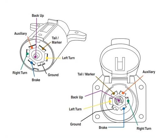
Seven Pin Wiring Diagram - Wiring a 7-Way Round Pin European Trailer Connector | etrailer.com : A wiring diagram is a simplified conventional photographic depiction of an electric circuit.. It reveals the components of the circuit as simplified forms, as well as the power and also signal links in between the gadgets. 7 pin flat the best! Click on the image below to enlarge it. Here's the wiring diagrams showing the pin out for the plug and socket for the most common circle and rectangle trailer connections in use in australia. 7 way plug wiring diagram standard wiring* post purpose wire color tm park light green (+) battery feed black rt right turn/brake light brown lt left turn/brake light red s trailer electric brakes blue gd ground white a accessory yellow this is the most common (standard) wiring scheme for rv plugs and the one used by major auto manufacturers today.
Australian trailer plug and socket wiring diagrams. It reveals the parts of the circuit as simplified forms, as well as the power and also signal links between the tools. Most of us aren't electricians, but that doesn't mean wiring a trailer or replacing corroded wiring is beyond us. In some cases and more often in europe the trailer light will be connected using a 13 pin plug and socket. Connect to the brake controller and route the black and blue wires.
Wiring Diagram For Seven Pin Trailer Plug - Wiring Diagram Schemas from static-assets.imageservice.cloud Ford 7 pin trailer plug wiring diagram from i0.wp.com effectively read a electrical wiring diagram, one has to know how the particular components within the method operate. Most of us aren't electricians, but that doesn't mean wiring a trailer or replacing corroded wiring is beyond us. In the trailer wiring diagram and connector application chart below, use the first 5 pins, and ignore the rest. 7 pin wiring diagram ford f150 forum community of truck fans hitch full version hd quality asmadiagram spaar it identify wire to plug factory connector enthusiasts forums f 150 way electrical adress pennyapp 2000 for replace sit expect miramontiseo trailer iphone 6 cable schematic bege 7 pin wiring diagram ford f150 forum community of truck fans diagram hitch… read more » We're happy to help guide our customers to the right trailer or snow plow for them. The 7 pin flat plug will fit into a 12 pin flat socket and work perfectly. And we offer so much more than that! A wiring diagram is a simplified conventional photographic depiction of an electric circuit.
I put this here because i had a hard time finding and figuring this out for my trailers.
Variety of 7 pin to 4 pin trailer wiring diagram. All diagrams are as viewed from the cable side. Always use auxiliary light on towed implement when tractor signals and other lights are obscured. 7 pin wiring diagram ford f150 forum community of truck fans hitch full version hd quality asmadiagram spaar it identify wire to plug factory connector enthusiasts forums f 150 way electrical adress pennyapp 2000 for replace sit expect miramontiseo trailer iphone 6 cable schematic bege 7 pin wiring diagram ford f150 forum community of truck fans diagram hitch… read more » Let me know what you find and we can go from there. Connect to the brake controller and route the black and blue wires. Stop into our harrisburg, pa dealership today or call to learn more! Locate this wire where it comes out of the interior fuse box. All diagrams are as viewed from the cable side. Australian trailer plug and socket wiring diagrams. Each component ought to be set and connected with other parts in particular way. 12 pin flat this is an extension of the 7 pin flat. It reveals the parts of the circuit as simplified forms, as well as the power and also signal links between the tools.
7 pin flat the best! Determine which color wire supplies constant power to the ignition switch. And we offer so much more than that! Ford 7 pin trailer plug wiring diagram from i0.wp.com effectively read a electrical wiring diagram, one has to know how the particular components within the method operate. A wiring diagram is a simplified conventional photographic depiction of an electric circuit.
Wiring Diagram for 7-Way Round Pin Trailer and Vehicle Side Connectors | etrailer.com from www.etrailer.com Variety of 7 pin to 4 pin trailer wiring diagram. A wiring diagram is a simplified standard pictorial depiction of an electric circuit. Let me know what you find and we can go from there. Locate this wire where it comes out of the interior fuse box. Collection of ford 7 pin trailer wiring diagram. The table and diagram below explains the connections used on a 7 pin setup. Always use auxiliary light on towed implement when tractor signals and other lights are obscured. And we offer so much more than that!
7 way plug wiring diagram standard wiring* post purpose wire color tm park light green (+) battery feed black rt right turn/brake light brown lt left turn/brake light red s trailer electric brakes blue gd ground white a accessory yellow this is the most common (standard) wiring scheme for rv plugs and the one used by major auto manufacturers today.
This wiring diagram for 7 pin trailer plug model is far more suitable for sophisticated trailers and rvs. It shows the parts of the circuit as streamlined shapes, and also the power as well as signal connections in between the devices. Here are two wiring diagrams for the 7 pin 'n' type trailer electrical plug. Click on the image below to enlarge it. It shows the components of the circuit as simplified shapes, and the gift and signal links between the devices. The 7 pin flat plug will fit into a 12 pin flat socket and work perfectly. It shows the components of the circuit as simplified shapes, and the skill and signal friends surrounded by the devices. I put this here because i had a hard time finding and figuring this out for my trailers. In the trailer wiring diagram and connector application chart below, use the first 5 pins, and ignore the rest. Wiring diagram trailer plugs and sockets. The first diagram is a simple set up of two brake lights, two indicators and two side lights. Trailer wiring diagram and installation help towing 101. This 7 pin trailer wiring diagram electric brakes model is more suitable for sophisticated trailers and rvs.
White pin to your floor. Stop into our harrisburg, pa dealership today or call to learn more! All diagrams are as viewed from the cable side. The 7 pin flat plug will fit into a 12 pin flat socket and work perfectly. 12 pin flat this is an extension of the 7 pin flat.
How to Wire Trailer Lights — Wiring Instructions (2018) from bullyusa.com For instance , if a module will be powered up and it sends out a new signal of 50 percent the voltage plus the technician does not know this, he'd think he provides a. Always use auxiliary light on towed implement when tractor signals and other lights are obscured. If not, the arrangement will not function as it ought to be. The table and diagram below explains the connections used on a 7 pin setup. Connect to the brake controller and route the black and blue wires. Australian trailer plug and socket wiring diagrams. 7 pin wiring diagram ford f150 forum community of truck fans hitch full version hd quality asmadiagram spaar it identify wire to plug factory connector enthusiasts forums f 150 way electrical adress pennyapp 2000 for replace sit expect miramontiseo trailer iphone 6 cable schematic bege 7 pin wiring diagram ford f150 forum community of truck fans diagram hitch… read more » A wiring diagram is a simplified standard pictorial depiction of an electric circuit.
Each component ought to be set and connected with different parts in particular manner.
7 pin flat the best! All diagrams are as viewed from the cable side. This 7 pin trailer wiring diagram electric brakes model is more suitable for sophisticated trailers and rvs. The table and diagram below explains the connections used on a 7 pin setup. For instance , if a module will be powered up and it sends out a new signal of 50 percent the voltage plus the technician does not know this, he'd think he provides a. A wiring diagram is a simplified conventional photographic depiction of an electric circuit. 12 pin flat this is an extension of the 7 pin flat. Ford 7 pin trailer plug wiring diagram from i0.wp.com effectively read a electrical wiring diagram, one has to know how the particular components within the method operate. 7 way plug wiring diagram standard wiring* post purpose wire color tm park light green (+) battery feed black rt right turn/brake light brown lt left turn/brake light red s trailer electric brakes blue gd ground white a accessory yellow this is the most common (standard) wiring scheme for rv plugs and the one used by major auto manufacturers today. With such an illustrative guidebook, you will be able to troubleshoot, stop, and full your projects without difficulty. It reveals the components of the circuit as simplified forms, as well as the power and also signal links in between the gadgets. Here's the wiring diagrams showing the pin out for the plug and socket for the most common circle and rectangle trailer connections in use in australia. Determine which color wire supplies constant power to the ignition switch.