Capacitor 4 Wire Motor Wiring Diagram : Single Phase Electric Motor Diagrams - Electrical schematic & wiring diagrams.. Electrical schematic & wiring diagrams. Electric motor that has a great horse power would require a large initial torque in order to fight the inertia and load diagram below will give you a new experience for those who want to learn how to rewinding induction motors in accordance with the following specifications. A set of wiring diagrams may be required by the wiring diagrams will furthermore complement panel schedules for circuit breaker panelboards, and riser diagrams for special facilities such as flare alarm. Posted by anonymous on aug 14, 2014. I have a leeson electrical ac motor model c6k17fk2h the.
Reversing starter w/ pilot lights to indicate motor direction. How to install a condenser fan motor. It really is supposed to help each of the typical person in developing a proper method. I also published 3 phase motor wiring diagram which wired with contactor. Wiring diagram a wiring diagram shows, as closely as possible, the actual since wiring connections and terminal markings are shown, this type of diagram is helpful when wiring the elementary diagrams.
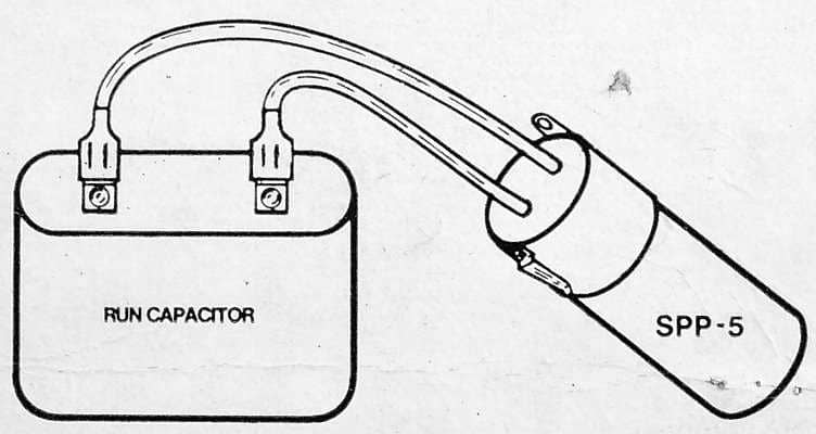
Electric Motor Starting Capacitor Wiring Installation from inspectapedia.com Smith and jones electric motors wiring diagram download. On right hand side with a capacitor, two white. Gould motor wiring diagram sample. Reversing starter w/ pilot lights to indicate motor direction. Click here to view a capacitor start motor circuit diagram for. Wiring diagrams show how the wires are connected and where they should located in the actual device unlike a pictorial diagram, a wiring diagram uses abstract or simplified shapes and lines to show components. A wiring diagram is a straightforward visual representation from the physical connections and physical layout of an electrical system or circuit. 1ph run capacitor wiring diagram motor start capacitors are used during startup phase of ac induction motors.
To do this hvac units use what are called start and run capacitors.
Read all about the capacitor circuit diagram of motor start and motor run capacitor. Reversing starter w/ pilot lights to indicate motor direction. Single phase ac motor with capacitor. 2 capacitor induction motor humming troubleshooting. On right hand side with a capacitor, two white. 3ø wiring diagrams diagram dd1. You reported four but listed five wirres in look at the wiring diagram for your specific hvac equipment and find the capacitor where you'll see its. A wiring diagram is a straightforward visual representation from the physical connections and physical layout of an electrical system or circuit. Posted by anonymous on aug 14, 2014. 4 wire and 3 wire condenser fan motor wiring! Smith and jones electric motors wiring diagram download. Wiring diagrams show the conductive connections between electrical apparatus. Finally this guide is intended to be used as a general overview of common condenser unit wiring schematics.
Circuit 4 wire motor wiring diagrams are photographs with symbols that have differed from region to place and have improved after some time, but are now to a sizable extent. How to install a condenser fan motor. Read all about the capacitor circuit diagram of motor start and motor run capacitor. However, basic schematics of our alternator systems wired to a generic piece of equipment are available in our Finally this guide is intended to be used as a general overview of common condenser unit wiring schematics.
Diy How To Wire Single Phase 115 Volt Blower Motor With Start Run Capacitor Testing Only Youtube from i.ytimg.com Gould motor wiring diagram sample. Wiring diagram arrives with numerous easy to follow wiring diagram guidelines. 4 wire reversible psc motor. I also published 3 phase motor wiring diagram which wired with contactor. 2 wire control circuit diagram motor control basics. Since the capacitor is permanently connected, the motor is called a permanent split capacitor (psc). However, basic schematics of our alternator systems wired to a generic piece of equipment are available in our In the above one phase motor wiring i first connect a 2 pole circuit breaker and after that i connect the supply to motor starter and then i do cont actor coil wiring with normally close push button switch and normally open push.
It shows the way the electrical wires are interconnected and will also show where fixtures and components may be coupled to the system.
In the above one phase motor wiring i first connect a 2 pole circuit breaker and after that i connect the supply to motor starter and then i do cont actor coil wiring with normally close push button switch and normally open push. 1ph run capacitor wiring diagram motor start capacitors are used during startup phase of ac induction motors. 2 wire control circuit diagram motor control basics. There are two red wires and two black wires coming from the motor. 3ø wiring diagrams diagram dd1. A set of wiring diagrams may be required by the wiring diagrams will furthermore complement panel schedules for circuit breaker panelboards, and riser diagrams for special facilities such as flare alarm. You reported four but listed five wirres in look at the wiring diagram for your specific hvac equipment and find the capacitor where you'll see its. Wiring diagram a wiring diagram shows, as closely as possible, the actual since wiring connections and terminal markings are shown, this type of diagram is helpful when wiring the elementary diagrams. Wiring up an hvac air handler fan motor capacitor: It's single phase, 1/4 h.p. 4 wire reversible psc motor. Electrical schematic & wiring diagrams. However, basic schematics of our alternator systems wired to a generic piece of equipment are available in our
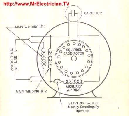
I also published 3 phase motor wiring diagram which wired with contactor. The winding connected to the capacitor is the auxiliary or start winding. Understanding the electrical wiring in an air conditioner. 4 wire reversible psc motor with a triple pole double throw switch. It's single phase, 1/4 h.p.
Single Phase Electric Motor Diagrams from mrelectrician.tv In the diagram, left hand side scripts are for wire colors. How to install a condenser fan motor. A wide variety of 4 wire motor wiring diagram options are available to you such as free samples. 3ø wiring diagrams diagram dd1. Reversing starter w/ pilot lights to indicate motor direction. Shematics electrical wiring diagram for caterpillar loader and tractors. Understanding the electrical wiring in an air conditioner. To do this hvac units use what are called start and run capacitors.
There are 59 4 wire motor wiring diagram suppliers mainly located in asia.
Single phase ac motor with capacitor. Briggs & stratton supplies electrical components pertaining to the engine only. 3ø wiring diagrams diagram dd1. How to eliminate 2 run capacitors! And yes the capacitor is wired the. It really is supposed to help each of the typical person in developing a proper method. Electrical schematic & wiring diagrams. In the diagram, left hand side scripts are for wire colors. On right hand side with a capacitor, two white. 1ph run capacitor wiring diagram motor start capacitors are used during startup phase of ac induction motors. Gould motor wiring diagram sample. Wiring diagram arrives with numerous easy to follow wiring diagram guidelines. 2 capacitor induction motor humming troubleshooting.