Wiring Diagram For Thermostat : 2 Stage Honeywell 6000 Thermostat Wiring Diagram - Wiring Forums - Thermostatic wiring principles by bob scaringe ph.d., p.e.. Use the wiring diagram the app gave you during setup to move the wires to the right connectors. Just take a look at the picture below the diagram. 3 phase contactor relay wiring diagram; We address them in order from most common to least common. In fact, the wiring of a thermostat is quite simple circuitry, the confusion arises principally because
24v trailer socket wiring diagram; In fact, the wiring of a thermostat is quite simple circuitry, the confusion arises principally because Feel free to jump to the section that covers your specific topic: However your connections may seem a little different on the thermostat itself. It shows how the electrical wires are interconnected and can also show where fixtures and components may be connected to the system.
Collection Of Nest thermostat 3rd Generation Wiring Diagram Download from worldvisionsummerfest.com 3 lamp t8 ballast wiring diagram; Feb 23, 2019 · 240v single pole circuit breaker wiring diagram; It shows how the electrical wires are interconnected and can also show where fixtures and components may be connected to the system. The red wire or 24 vac power lead is connected straight to the rc & 4 terminals. Feb 04, 2021 · wiring diagrams use simplified symbols to represent switches, lights, outlets, etc. Feel free to jump to the section that covers your specific topic: However your connections may seem a little different on the thermostat itself. Always refer to your thermostat or equipment installation guides to verify proper wiring.
Just take a look at the picture below the diagram.
Feb 04, 2021 · wiring diagrams use simplified symbols to represent switches, lights, outlets, etc. 24v 8 pin relay wiring diagram; Here is the wiring symbol legend, which is a detailed documentation of common symbols that are used in wiring diagrams, home wiring plans, and electrical wiring blueprints. However your connections may seem a little different on the thermostat itself. 3 phase contactor wiring diagram start stop Use the wiring diagram the app gave you during setup to move the wires to the right connectors. The red wire or 24 vac power lead is connected straight to the rc & 4 terminals. 277 volt single phase wiring diagram; Color of wire and termination: 3 phase contactor relay wiring diagram; 3 lamp t8 ballast wiring diagram; This is unlike a schematic diagram , where the arrangement of the components' interconnections on the diagram usually does not correspond to the components' physical. A wiring diagram usually gives information about the relative position and arrangement of devices and terminals on the devices, to help in building or servicing the device.
240v single pole thermostat wiring diagram; 3 phase contactor relay wiring diagram; 3 phase contactor wiring diagram start stop A wiring diagram is a simple visual representation of the physical connections and physical layout of an electrical system or circuit. In fact, the wiring of a thermostat is quite simple circuitry, the confusion arises principally because
Find Out Here Honeywell Manual thermostat Wiring Diagram Sample from worldvisionsummerfest.com Thermostat condenser furnace some ac systems will have a blue wire with a pink stripe in place of the yellow or y wire. Feb 04, 2021 · wiring diagrams use simplified symbols to represent switches, lights, outlets, etc. Here is the wiring symbol legend, which is a detailed documentation of common symbols that are used in wiring diagrams, home wiring plans, and electrical wiring blueprints. 277 volt single phase wiring diagram; Always refer to your thermostat or equipment installation guides to verify proper wiring. Note o o o o o o 1 2 3 3 phase contactor relay wiring diagram; It is a red wire and comes from the transformer usually located in the air handler for split systems, but you may find the transformer in the condensing unit.
24v trailer socket wiring diagram;
Many technicians have great difficulty understanding how to properly wire a thermostat or how to replace a thermostat with a different thermostat. 277 volt single phase wiring diagram; If you don't have the wiring diagram, refer to the picture of your thermostat wires that you took We address them in order from most common to least common. Color of wire and termination: 3 lamp t8 ballast wiring diagram; 24v 8 pin relay wiring diagram; The red wire or 24 vac power lead is connected straight to the rc & 4 terminals. A wiring diagram usually gives information about the relative position and arrangement of devices and terminals on the devices, to help in building or servicing the device. In fact, the wiring of a thermostat is quite simple circuitry, the confusion arises principally because This is unlike a schematic diagram , where the arrangement of the components' interconnections on the diagram usually does not correspond to the components' physical. 3 phase contactor relay wiring diagram; 2jz spark plug wire diagram;
3 lamp t8 ballast wiring diagram; A wiring diagram is a simple visual representation of the physical connections and physical layout of an electrical system or circuit. It is a red wire and comes from the transformer usually located in the air handler for split systems, but you may find the transformer in the condensing unit. 3 phase contactor relay wiring diagram; Just take a look at the picture below the diagram.
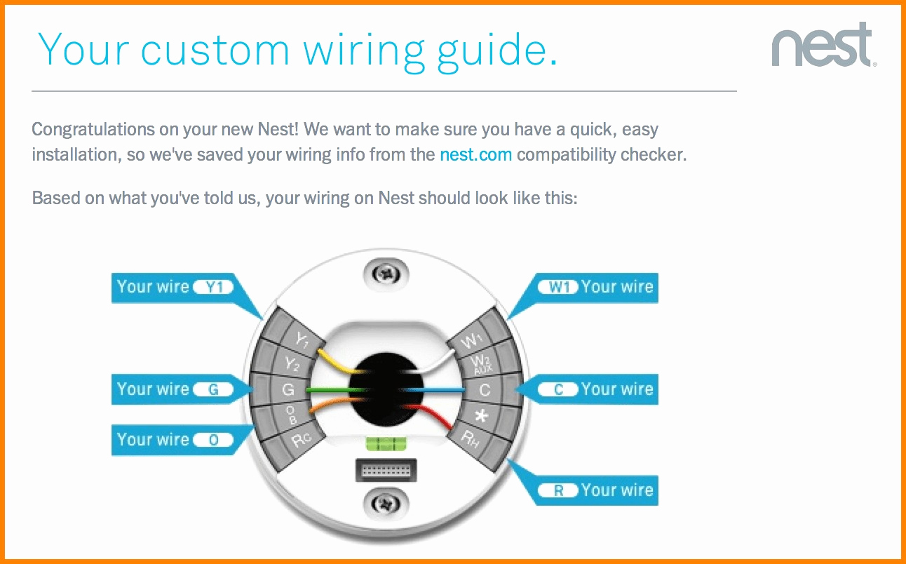
Wiring Diagram For Nest Thermostat | Wiring Diagram from annawiringdiagram.com We address them in order from most common to least common. Use the wiring diagram the app gave you during setup to move the wires to the right connectors. Turn off power to your system and thermostat at the breaker or fuse box. Here is the wiring symbol legend, which is a detailed documentation of common symbols that are used in wiring diagrams, home wiring plans, and electrical wiring blueprints. 3 lamp t8 ballast wiring diagram; 24v 8 pin relay wiring diagram; If you don't have the wiring diagram, refer to the picture of your thermostat wires that you took 240v single pole thermostat wiring diagram;
If you don't have the wiring diagram, refer to the picture of your thermostat wires that you took
In fact, the wiring of a thermostat is quite simple circuitry, the confusion arises principally because 277 volt single phase wiring diagram; If you don't have the wiring diagram, refer to the picture of your thermostat wires that you took It shows how the electrical wires are interconnected and can also show where fixtures and components may be connected to the system. Here is the wiring symbol legend, which is a detailed documentation of common symbols that are used in wiring diagrams, home wiring plans, and electrical wiring blueprints. Thermostatic wiring principles by bob scaringe ph.d., p.e. A wiring diagram usually gives information about the relative position and arrangement of devices and terminals on the devices, to help in building or servicing the device. However your connections may seem a little different on the thermostat itself. Feb 23, 2019 · 240v single pole circuit breaker wiring diagram; Color of wire and termination: 24v 8 pin relay wiring diagram; 3 lamp t8 ballast wiring diagram; Thermostat condenser furnace some ac systems will have a blue wire with a pink stripe in place of the yellow or y wire.