Home
› Cross Over Cable Diagram - Crossover Cable Pinout Diagram Sun Rack Ii Power Distribution Units User S Guide - The diagram below shows a standard usb cable connection with its internal four wires and their function.
Cross Over Cable Diagram - Crossover Cable Pinout Diagram Sun Rack Ii Power Distribution Units User S Guide - The diagram below shows a standard usb cable connection with its internal four wires and their function.
Cross Over Cable Diagram - Crossover Cable Pinout Diagram Sun Rack Ii Power Distribution Units User S Guide - The diagram below shows a standard usb cable connection with its internal four wires and their function.. One trick that we 2 to print a similar wiring picture off twice. These cables are sometimes made with a cable that has a red outer sheath. A distribution block is a good way to get power for your crossover via the same main power cable as the amp uses. T1e1j1 schematron.org t1 cables use four wires: The diagram below shows a standard usb cable connection with its internal four wires and their function.
In that case the crossover frequency would shift downward 2 x the original value (example: One end uses the t568a wiring standard, and the other end uses the t568b wiring standard. Crossover cable, as the name suggests, cross over or swap on its way when coming from one end to the other. So just check your cable on both end and make sure it matches the diagram. The simplest crossover circuit usually occurs with the addition of a tweeter to a woofer.
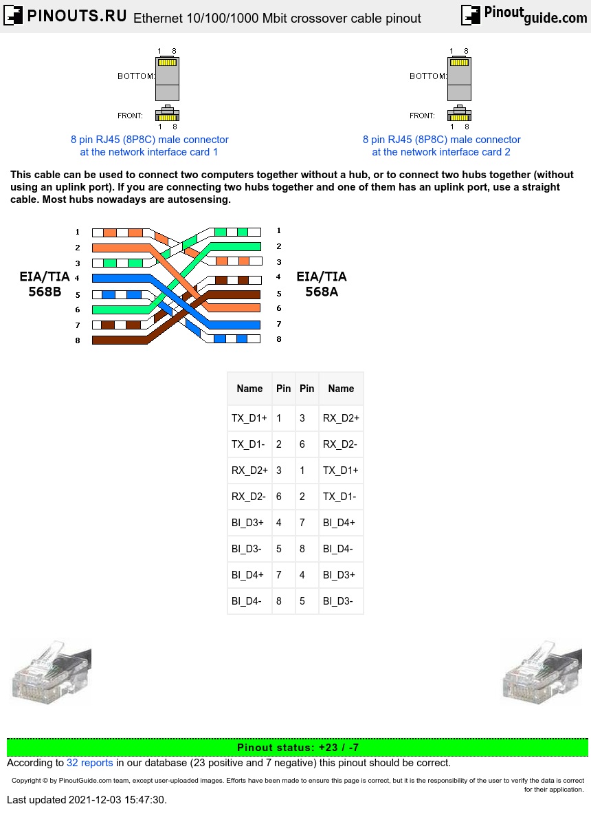
Ethernet 10 100 1000 Mbit Crossover Cable Pinout Diagram Pinouts Ru from pinouts.ru A null modem or crossover cable is used to connect to dte devices together. Two computers (via their network interface controllers) or two switches to each other.by contrast, straight through patch cables are used to connect devices of different types, such as a computer to a network switch. Diy audio speaker crossover wiring guide / faq see the crossover example tutorial for more information. Wiring diagram electrical wires cable audio crossover schematic engineering png 680x386px amplifier. T1e1j1 schematron.org t1 cables use four wires: The only pins that need to be crossed are 1,3 and 2,6. Care must be taken to identify a crossover cable clearly so it is not used by mistake as this may cause network outages. These cables are sometimes made with a cable that has a red outer sheath.
As a matter of caution aa usb cables may burn the usb ports and the power supplies connected.
There is no one speaker capable of producing all frequencies throughout this range. Be sure not to strip or damage any of the pairs of inner cables. An ethernet crossover cable is a crossover cable for ethernet used to connect computing devices together directly. Two computers (via their network interface controllers) or two switches to each other.by contrast, straight through patch cables are used to connect devices of different types, such as a computer to a network switch. T1/e1/j1 rj48 cable diagram the following illustration provides the wiring connections for straight or crossover cables. Print the wiring diagram off and use highlighters in order to trace the circuit. As an example, wiring an 8 ohm home speaker to a 4 ohm car speaker crossover won't work right. It is most often used to connect two devices of the same type, e.g. A crossover cable is a type of cat 5 where one end ist568a configuration and the other end as t568bconfiguration. The transmit pins on each connector are connected to the receive pins which is at the other end of the cable. Cat5 cabling diagram cat5 stripping and terminate ch 1 recommended cat55e rj45 cable assemblies for use with lantronix device servers. Diy audio speaker crossover wiring guide / faq see the crossover example tutorial for more information. The simplest crossover circuit usually occurs with the addition of a tweeter to a woofer.
For this to work, the transmit (txd) pin of one device needs to be connected to the receive (rxd) pin of the other device, and vice versa. T1e1j1 schematron.org t1 cables use four wires: Be sure not to strip or damage any of the pairs of inner cables. The other is to expand a network by connecting another network switch, thereby giving you more ports. The internal wiring of crossover cables reverses the transmission and.
Ethernet Crossover Cable Wikipedia from upload.wikimedia.org This is the simplest type of network usually found in. When you use your finger or even follow the circuit along with your eyes, it's easy to mistrace the circuit. Crossover cables are most commonly used to connect two hosts directly. The diagram above describes the various color coding and pin outs for the network cabling and the rj45 modular connector. It is also possible to wire it the opposite way (i.e., straight through is a t568a). Cat5 cabling diagram cat5 stripping and terminate ch 1 recommended cat55e rj45 cable assemblies for use with lantronix device servers. The internal wiring of crossover cables reverses the transmission and. Connecting a lan port to a switch, hub, or computer.
When you use your finger or even follow the circuit along with your eyes, it's easy to mistrace the circuit.
If you are creating a crossover cable, please click here for the crossover cable diagram. Null modem cable with handshake. Care must be taken to identify a crossover cable clearly so it is not used by mistake as this may cause network outages. A crossover cable is a type of cat 5 where one end ist568a configuration and the other end as t568bconfiguration. Be sure not to strip or damage any of the pairs of inner cables. The simplest crossover circuit usually occurs with the addition of a tweeter to a woofer. One trick that we 2 to print a similar wiring picture off twice. You can get a cheap 10ft crossover cable on amazon for $5 or you can get crossover adapters, which are a little bit more, but can turn any ethernet cable into a crossover cable. An ethernet crossover cable is a crossover cable for ethernet used to connect computing devices together directly. T1/e1/j1 rj48 cable diagram the following illustration provides the wiring connections for straight or crossover cables. That's because the crossover is designed using math & parts based on using a 4ω speaker load. Connecting a lan port to a switch, hub, or computer. The above diagram says, how the communication is not possible.
Unlike patch cable, crossover cable uses two different wiring standards on both end: Be sure not to strip or damage any of the pairs of inner cables. Crossover cable, as the name suggests, cross over or swap on its way when coming from one end to the other. Two computers (via their network interface controllers) or two switches to each other.by contrast, straight through patch cables are used to connect devices of different types, such as a computer to a network switch. The diagram below shows a standard usb cable connection with its internal four wires and their function.
The Difference Between Straight Through Crossover And Rollover Cables from learn-networking.com Be sure not to strip or damage any of the pairs of inner cables. The transmit pins on each connector are connected to the receive pins which is at the other end of the cable. Crossover cable color code tia 568b the following table illustrates tia 568b color coding scheme which is applied on the left end of the cable in crossover cable wiring diagram. Null modem cable with handshake. A crossover lan cable will connect the receive at one end to the transmit at the other. T1e1j1 schematron.org t1 cables use four wires: So just check your cable on both end and make sure it matches the diagram. Cat5 cabling diagram cat5 stripping and terminate ch 1 recommended cat55e rj45 cable assemblies for use with lantronix device servers.
A 3.5khz crossover frequency would shift to 1.75khz).
The transmit pins on each connector are connected to the receive pins which is at the other end of the cable. How to wire tweeters with a built in an eq and crossover for car audio systems application diagrams audiocontrol amplifier wiring add diamond technology d6 1 system diagram digital 2 channel mosfet front speaker crossovers ih8mud forum bridge amp faq 4 electrical wires cable speakers sub rear. T1e1j1 schematron.org t1 cables use four wires: In this type of cable connection, pin 1 is crossed with pin 3, and pin 2 is crossed with pin 6. Crossover cables are most commonly used to connect two hosts directly. Null modem cable with handshake. Cat5e is certified for gigabit support, but cat5 cabling works as well, just over shorter distances. Unlike patch cable, crossover cable uses two different wiring standards on both end: A distribution block is a good way to get power for your crossover via the same main power cable as the amp uses. A crossover lan cable will connect the receive at one end to the transmit at the other. Connecting a computer to a swtich. The internal wiring of crossover cables reverses the transmission and. The diagram above describes the various color coding and pin outs for the network cabling and the rj45 modular connector.